
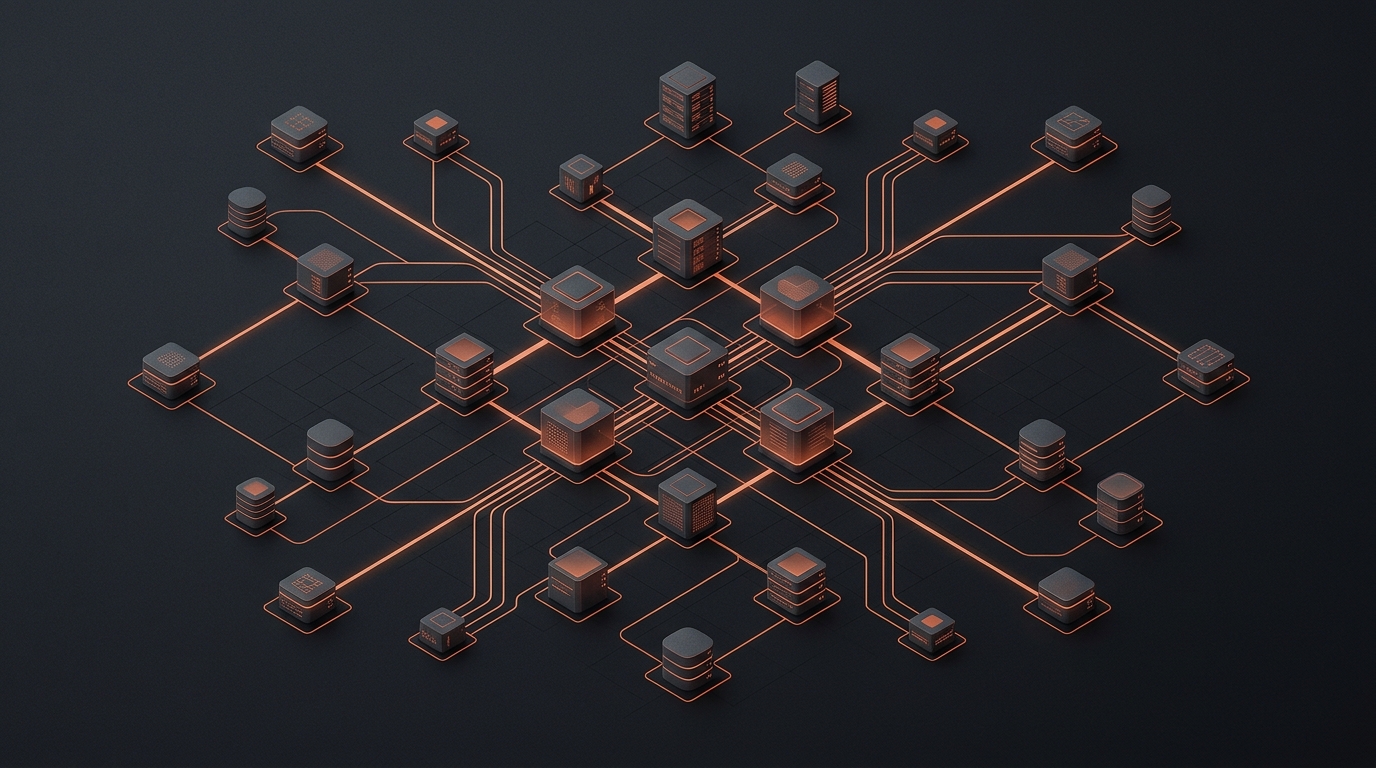
Architectural documentation is often the first casualty of rapid development cycles. When systems evolve daily, manual diagramming in tools like Draw.io or Lucidchart becomes a significant bottleneck, leading to stale documentation that misleads stakeholders and new engineers alike. The solution lies in shifting from ‘drawing’ to ‘generating’—treating [[[architecture](/blog/is-super-app-capability-only-for-tech-giants-a-practical-architecture-for-starting-small)](/blog/building-a-scalable-e-commerce-platform-architecture-decisions-that-actually-matter)](/blog/why-enterprise-architecture-diagrams-dont-solve-operational-problems) diagrams as artifacts of your codebase.
By adopting a batch-generation pattern, engineering teams can synchronize their visual documentation with the actual state of their infrastructure. This approach leverages existing configuration files, such as Terraform HCL or Kubernetes manifests, to programmatically render diagrams that are always accurate.
The Architecture-as-Code Foundation
The prerequisite for batch generation is a centralized source of truth. If your infrastructure is defined in Terraform, you already possess the graph data needed for visualization. Tools like ‘terraform-graph’ or ‘terravision’ can parse the state or plan files into DOT format, which serves as the intermediate language for diagram generators.
To scale this to 20+ diagrams, you must abstract the generation logic into a unified pipeline. Instead of running commands manually, integrate a CI/CD job that triggers on merge requests to the infrastructure repository. This ensures that every architectural change is accompanied by an updated visual representation.
Designing the Batch Pipeline
A robust generation pipeline consists of three distinct stages: Extraction, Transformation, and Rendering. In the extraction phase, you traverse the repository to identify service boundaries or cloud resource groupings. The transformation phase converts these groupings into a domain-specific language (DSL) like Mermaid.js or PlantUML.
const generateDiagrams = async (services) => {
  for (const service of services) {
    const definition = await parseTerraformConfig(service.path);
    const mermaidCode = convertToMermaid(definition);
    await fs.writeFile(`./docs/diagrams/${service.name}.mmd`, mermaidCode);
    await renderToPng(`./docs/diagrams/${service.name}.mmd`);
  }
};
The rendering phase is where you manage the batch aspect. By using headless browser engines or CLI-based renderers, you can process dozens of diagrams in parallel. This prevents the pipeline from becoming a time sink for engineers.
Trade-offs and Limitations
- Layout Non-determinism: Automatic layout algorithms sometimes produce sub-optimal results for complex, highly-connected graphs.
- Loss of Context: Code-generated diagrams often lack the ‘business logic’ context that a human-designed diagram might emphasize.
- Maintenance Overhead: You are essentially building and maintaining an internal developer tool, which requires its own testing and update cycle.
Implementing Quality Gates
Just as you run linters on your application code, you should run validation on your diagram definitions. If the generated diagram exceeds a certain node density or complexity threshold, the CI pipeline should flag it for manual review. This prevents ‘spaghetti diagrams’ from being committed to the documentation repository.
The goal of automated diagramming is not to replace human architectural thought, but to eliminate the manual labor of maintaining visual artifacts that reflect reality.
Conclusion
Batch-generating architecture diagrams is a high-leverage strategy for teams managing complex distributed systems. By treating diagrams as code, you ensure that your documentation remains a reliable asset rather than a liability. While the initial investment in building the generator is non-trivial, the long-term payoff in developer velocity and architectural clarity is substantial.